Membrane valve, branching outlets
One round chamber covered by a flexible sheet, with an air line above it. Air pressure presses the sheet down onto the chamber floor and closes it. This version feeds several outlets, which leave the chamber wall directly and fan out to points around a ring.
What it is for. Splitting one liquid supply into several destinations, or shutting all of them at once with a single air line.
Variants
Sizes below are given in px: units of the design grid these parts were drawn on, where one unit is 0.0076 mm. That is not the printer's pixel. The printer has its own, different pixel size, and nothing on this page is expressed in it — see Hardware and process.
Showing one variant at a time. All of them are on this page.
CH1_100px_3out_0
H.R.3.3 design
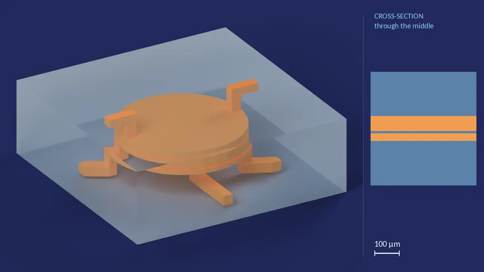
| Valve diameter | 100 px |
|---|---|
| Where liquid enters the chamber | Edge |
| Number of outlets | 3 |
| Membrane thickness | 1 layer |
| Fluid chamber height | 3 layers |
| Air chamber height | 6 layers |
| Channel cross-section | 8 px × 6 layers |
| Footprint | 180 × 180 px |
| Ports | 1 fluid in, 3 fluid out, 1 air in, 1 air out |
| Layout grid | 0.0076 mm per px |
Files for this variant
CH1_100px_4out_0
H.R.3.3 design
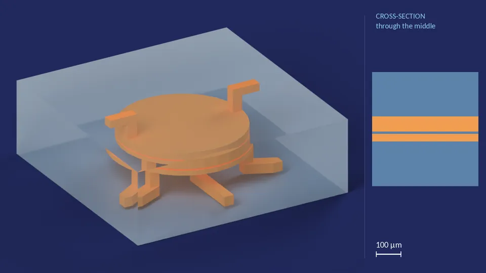
| Valve diameter | 100 px |
|---|---|
| Where liquid enters the chamber | Edge |
| Number of outlets | 4 |
| Membrane thickness | 1 layer |
| Fluid chamber height | 3 layers |
| Air chamber height | 6 layers |
| Channel cross-section | 8 px × 6 layers |
| Footprint | 180 × 180 px |
| Ports | 1 fluid in, 4 fluid out, 1 air in, 1 air out |
| Layout grid | 0.0076 mm per px |
Files for this variant
CH1_100px_5out_0
H.R.3.3 design
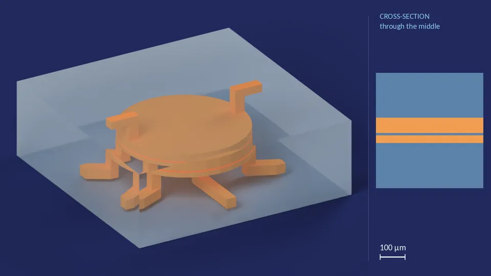
| Valve diameter | 100 px |
|---|---|
| Where liquid enters the chamber | Edge |
| Number of outlets | 5 |
| Membrane thickness | 1 layer |
| Fluid chamber height | 3 layers |
| Air chamber height | 6 layers |
| Channel cross-section | 8 px × 6 layers |
| Footprint | 180 × 180 px |
| Ports | 1 fluid in, 5 fluid out, 1 air in, 1 air out |
| Layout grid | 0.0076 mm per px |
Files for this variant
CH1_100px_6out_0
H.R.3.3 design
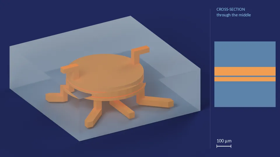
| Valve diameter | 100 px |
|---|---|
| Where liquid enters the chamber | Edge |
| Number of outlets | 6 |
| Membrane thickness | 1 layer |
| Fluid chamber height | 3 layers |
| Air chamber height | 6 layers |
| Channel cross-section | 8 px × 6 layers |
| Footprint | 180 × 180 px |
| Ports | 1 fluid in, 6 fluid out, 1 air in, 1 air out |
| Layout grid | 0.0076 mm per px |
Files for this variant
CH1_100px_7out_0
H.R.3.3 design
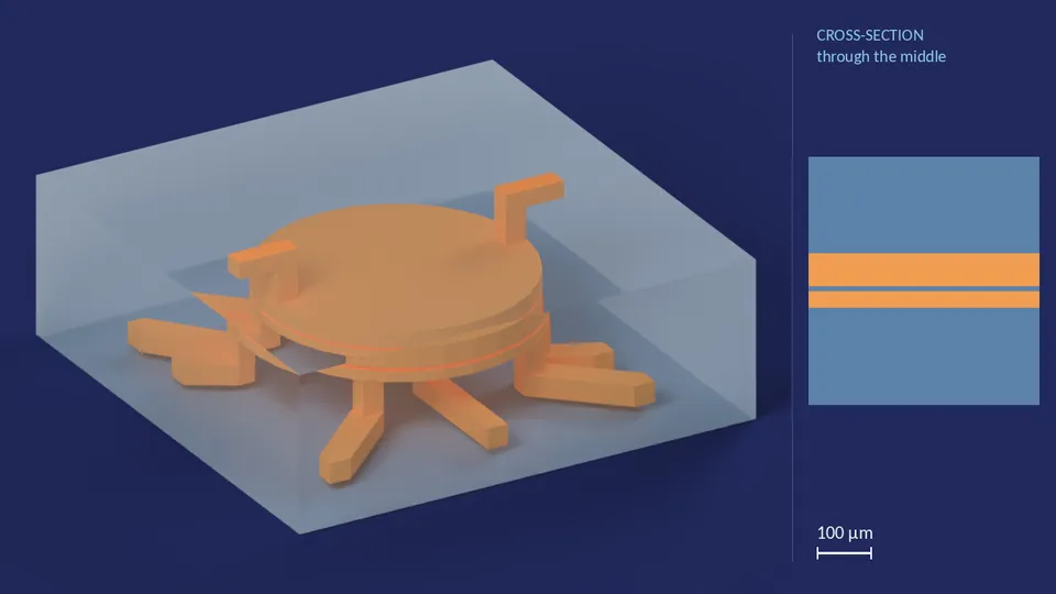
| Valve diameter | 100 px |
|---|---|
| Where liquid enters the chamber | Edge |
| Number of outlets | 7 |
| Membrane thickness | 1 layer |
| Fluid chamber height | 3 layers |
| Air chamber height | 6 layers |
| Channel cross-section | 8 px × 6 layers |
| Footprint | 180 × 180 px |
| Ports | 1 fluid in, 7 fluid out, 1 air in, 1 air out |
| Layout grid | 0.0076 mm per px |
Files for this variant
CH1_100px_8out_0
H.R.3.3 design
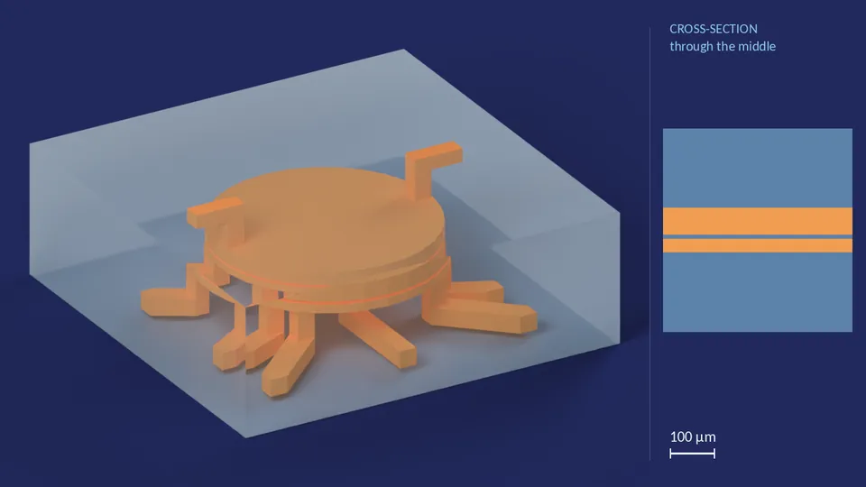
| Valve diameter | 100 px |
|---|---|
| Where liquid enters the chamber | Edge |
| Number of outlets | 8 |
| Membrane thickness | 1 layer |
| Fluid chamber height | 3 layers |
| Air chamber height | 6 layers |
| Channel cross-section | 8 px × 6 layers |
| Footprint | 180 × 180 px |
| Ports | 1 fluid in, 8 fluid out, 1 air in, 1 air out |
| Layout grid | 0.0076 mm per px |
Files for this variant
CH1_40px_3out_0
H.R.3.3 design
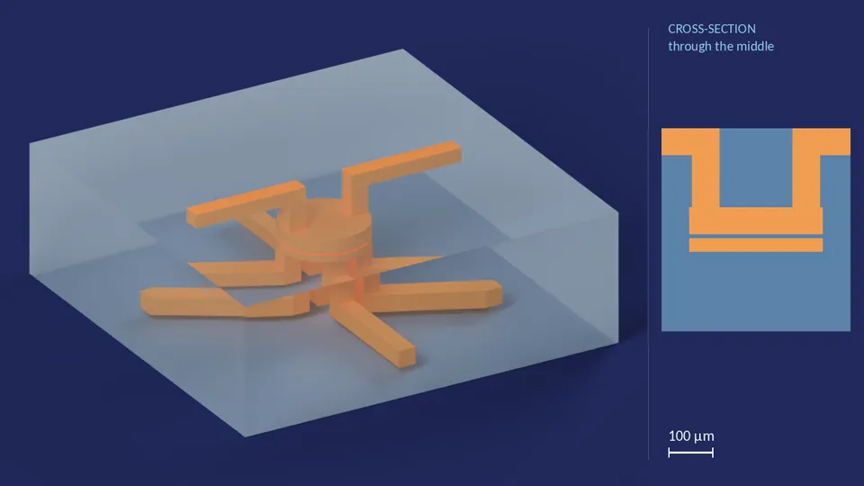
| Valve diameter | 40 px |
|---|---|
| Where liquid enters the chamber | Edge |
| Number of outlets | 3 |
| Membrane thickness | 1 layer |
| Fluid chamber height | 3 layers |
| Air chamber height | 6 layers |
| Channel cross-section | 8 px × 6 layers |
| Footprint | 180 × 180 px |
| Ports | 1 fluid in, 3 fluid out, 1 air in, 1 air out |
| Layout grid | 0.0076 mm per px |
Files for this variant
CH1_40px_4out_0
H.R.3.3 design
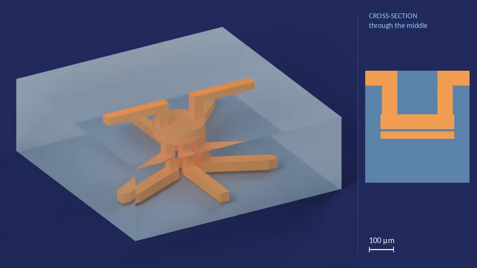
| Valve diameter | 40 px |
|---|---|
| Where liquid enters the chamber | Edge |
| Number of outlets | 4 |
| Membrane thickness | 1 layer |
| Fluid chamber height | 3 layers |
| Air chamber height | 6 layers |
| Channel cross-section | 8 px × 6 layers |
| Footprint | 180 × 180 px |
| Ports | 1 fluid in, 4 fluid out, 1 air in, 1 air out |
| Layout grid | 0.0076 mm per px |
Files for this variant
CH1_40px_5out_0
H.R.3.3 design
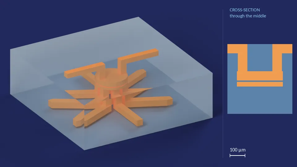
| Valve diameter | 40 px |
|---|---|
| Where liquid enters the chamber | Edge |
| Number of outlets | 5 |
| Membrane thickness | 1 layer |
| Fluid chamber height | 3 layers |
| Air chamber height | 6 layers |
| Channel cross-section | 8 px × 6 layers |
| Footprint | 180 × 180 px |
| Ports | 1 fluid in, 5 fluid out, 1 air in, 1 air out |
| Layout grid | 0.0076 mm per px |
Files for this variant
CH1_40px_7out_0
H.R.3.3 design
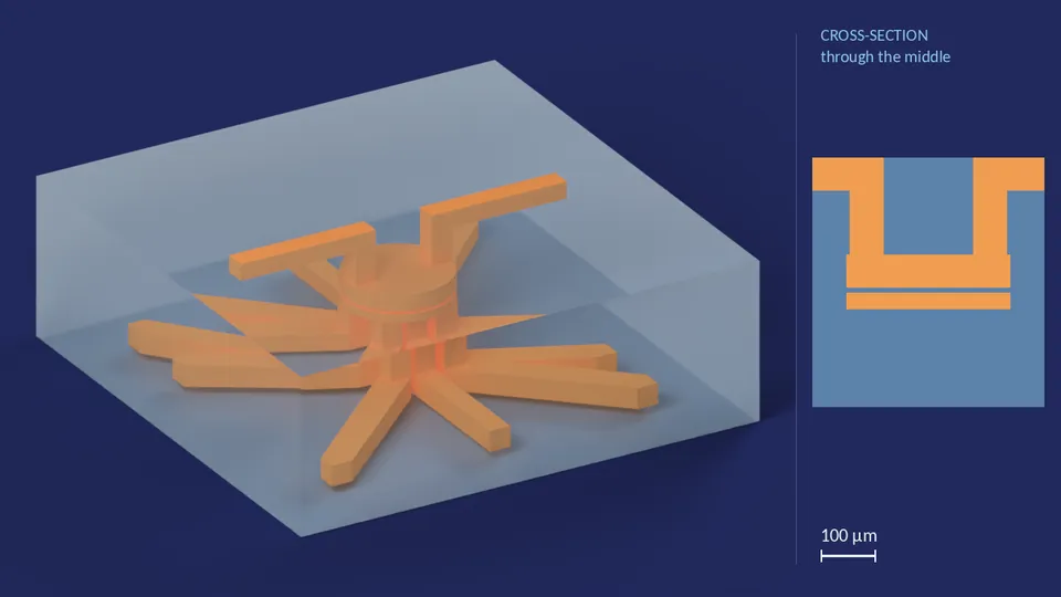
| Valve diameter | 40 px |
|---|---|
| Where liquid enters the chamber | Edge |
| Number of outlets | 7 |
| Membrane thickness | 1 layer |
| Fluid chamber height | 3 layers |
| Air chamber height | 6 layers |
| Channel cross-section | 8 px × 6 layers |
| Footprint | 180 × 180 px |
| Ports | 1 fluid in, 7 fluid out, 1 air in, 1 air out |
| Layout grid | 0.0076 mm per px |
Files for this variant
CH1_80px_3out_0
H.R.3.3 design
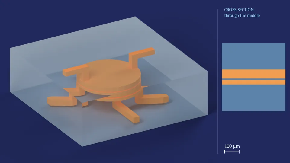
| Valve diameter | 80 px |
|---|---|
| Where liquid enters the chamber | Edge |
| Number of outlets | 3 |
| Membrane thickness | 1 layer |
| Fluid chamber height | 3 layers |
| Air chamber height | 6 layers |
| Channel cross-section | 8 px × 6 layers |
| Footprint | 180 × 180 px |
| Ports | 1 fluid in, 3 fluid out, 1 air in, 1 air out |
| Layout grid | 0.0076 mm per px |
Files for this variant
CH1_80px_4out_0
H.R.3.3 design
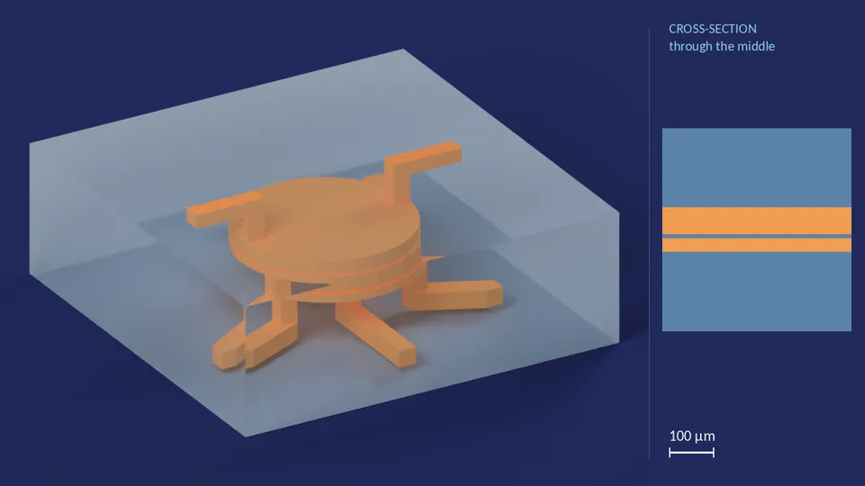
| Valve diameter | 80 px |
|---|---|
| Where liquid enters the chamber | Edge |
| Number of outlets | 4 |
| Membrane thickness | 1 layer |
| Fluid chamber height | 3 layers |
| Air chamber height | 6 layers |
| Channel cross-section | 8 px × 6 layers |
| Footprint | 180 × 180 px |
| Ports | 1 fluid in, 4 fluid out, 1 air in, 1 air out |
| Layout grid | 0.0076 mm per px |
Files for this variant
CH1_80px_5out_0
H.R.3.3 design
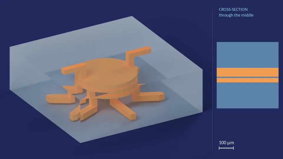
| Valve diameter | 80 px |
|---|---|
| Where liquid enters the chamber | Edge |
| Number of outlets | 5 |
| Membrane thickness | 1 layer |
| Fluid chamber height | 3 layers |
| Air chamber height | 6 layers |
| Channel cross-section | 8 px × 6 layers |
| Footprint | 180 × 180 px |
| Ports | 1 fluid in, 5 fluid out, 1 air in, 1 air out |
| Layout grid | 0.0076 mm per px |
Files for this variant
CH1_80px_6out_0
H.R.3.3 design
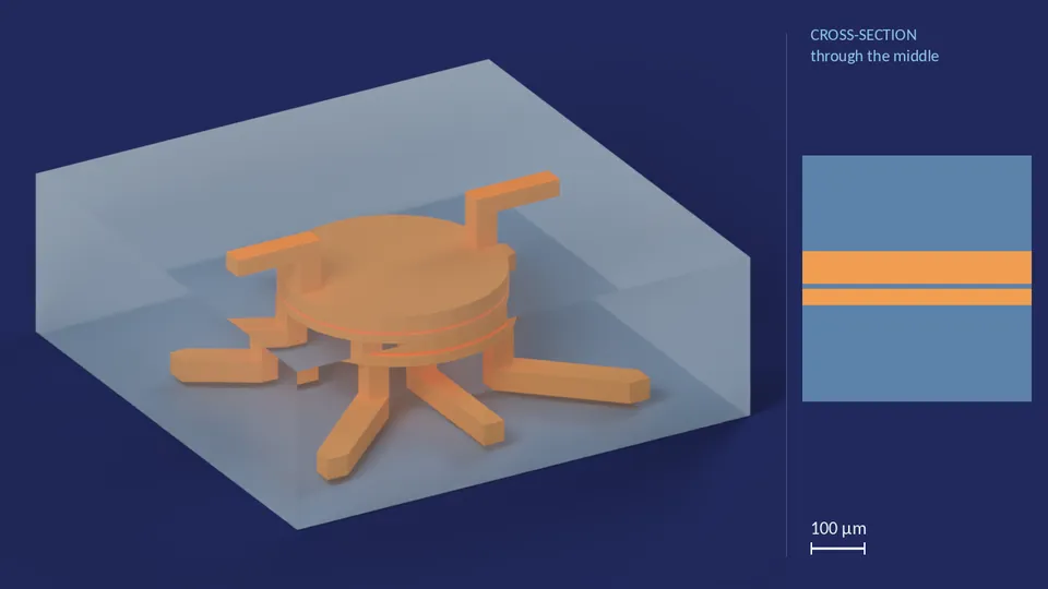
| Valve diameter | 80 px |
|---|---|
| Where liquid enters the chamber | Edge |
| Number of outlets | 6 |
| Membrane thickness | 1 layer |
| Fluid chamber height | 3 layers |
| Air chamber height | 6 layers |
| Channel cross-section | 8 px × 6 layers |
| Footprint | 180 × 180 px |
| Ports | 1 fluid in, 6 fluid out, 1 air in, 1 air out |
| Layout grid | 0.0076 mm per px |
Files for this variant
CH1_80px_7out_0
H.R.3.3 design
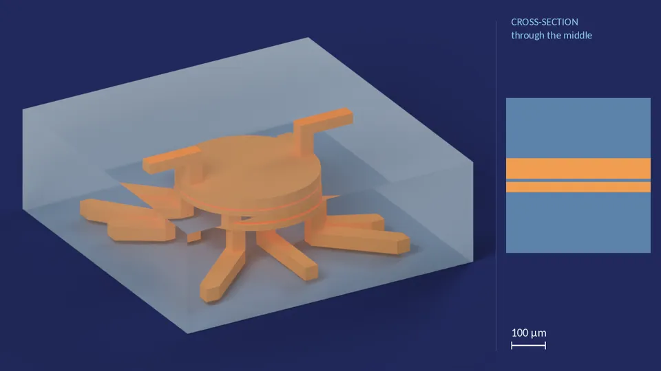
| Valve diameter | 80 px |
|---|---|
| Where liquid enters the chamber | Edge |
| Number of outlets | 7 |
| Membrane thickness | 1 layer |
| Fluid chamber height | 3 layers |
| Air chamber height | 6 layers |
| Channel cross-section | 8 px × 6 layers |
| Footprint | 180 × 180 px |
| Ports | 1 fluid in, 7 fluid out, 1 air in, 1 air out |
| Layout grid | 0.0076 mm per px |
Files for this variant
CH1_80px_8out_0
H.R.3.3 design
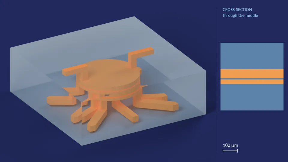
| Valve diameter | 80 px |
|---|---|
| Where liquid enters the chamber | Edge |
| Number of outlets | 8 |
| Membrane thickness | 1 layer |
| Fluid chamber height | 3 layers |
| Air chamber height | 6 layers |
| Channel cross-section | 8 px × 6 layers |
| Footprint | 180 × 180 px |
| Ports | 1 fluid in, 8 fluid out, 1 air in, 1 air out |
| Layout grid | 0.0076 mm per px |